画像の場合、二次元となります。
DCTの詳しい内容については、"Discrete Cosine Transform" でインターネットで検索してください。
Discrete Cosine Transform
DCT(離散コサイン変換)
音楽、画像、動画等で利用されているDCTについて、取り上げてみました。
此処では、単にDCTのみで、量子化とか、圧縮については取り上げていません。
DFT、FFTは、SINとCOSの両方の変換を行っていますが、DCTの場合はCOSの変換しか行いません。
COSのみでも、変換、逆変換で元のデーターを復元することが出来ます。
量子化、圧縮を行った場合は、非可逆圧縮となり完全には元のデーターに戻りません。
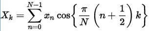
DCTの基本計算式は次のようなものですが、
画像の場合、二次元となります。
DCTの詳しい内容については、"Discrete Cosine Transform" でインターネットで検索してください。
プログラム 変換部分
// Cos変換
// inv False 変換 True 逆変換
procedure TForm1.DCT(var real: D2array; inv: boolean);
var
  M2                : Double;
  norm              : Double;
  startX            : integer;
  Tre               : D2array;
  WrTable           : D2array;
  HrTable           : D2array;
  i, j, y, x, xx, yy: Integer;
begin
  // 作業用配列確保
  SetLength(Tre, X_SIZE, Y_SIZE);
  SetLength(WrTable, X_SIZE, X_SIZE);
  SetLength(HrTable, Y_SIZE, Y_SIZE);

  // X軸方向DCT
  M2 :=   PI / X_SIZE;
  norm := 1;
  startX := 0;
  if inv then begin
    norm := 2.0 / X_SIZE;
    startX := 1;
  end;
  // 変換テーブル生成 直流、低い周波数から 高いほうへ設定
  for i := 0 to X_SIZE - 1 do
    for j := startx to X_SIZE - 1 do begin
      if inv then Wrtable[i][j] := cos(M2 * (i + 0.5) * j)
             else Wrtable[i][j] := cos(M2 * (j + 0.5) * i);
//  変換テーブル計算式は下記ですが高速化の為割り算をなくしています
//      if inv then Wrtable[i][j] := cos(pi * j / 2 / X_SIZE * (2 * i + 1))
//             else Wrtable[i][j] := cos(pi * i / 2 / X_SIZE * (2 * j + 1));
    end;
  // y軸毎に変換
  for y := 0 to Y_SIZE - 1 do
    // 一次元DCT
    for x := 0 to X_SIZE - 1 do begin
      Tre[x][y] := 0.0;
      for xx := startx to X_SIZE - 1 do
        Tre[x][y] := Tre[x][y] + real[xx][y] * Wrtable[x][xx];
      if inv then Tre[x][y] := Tre[x][y] + real[0][y] * 0.5;    // 直流分
      Tre[x][y] := Tre[x][y] * norm;
    end;

  // Y軸方向DCT
  M2 :=   PI / Y_SIZE;
  if inv then norm := 2.0 / Y_SIZE;
  // 変換テーブル生成 直流、低い周波数から 高いほうへ設定
  for i := 0 to Y_SIZE - 1 do
    for j := startx to Y_SIZE - 1 do begin
      if inv then Hrtable[i][j] := cos(M2 * (i + 0.5) * j)
             else Hrtable[i][j] := cos(M2 * (j + 0.5) * i);
//  変換テーブル計算式は下記ですが高速化の為割り算をなくしています
//      if inv then Hrtable[i][j] := cos(pi * j / 2 / Y_SIZE * (2 * i + 1))
//             else Hrtable[i][j] := cos(pi * i / 2 / Y_SIZE * (2 * j + 1));
    end;
  // X軸毎に変換
  for x := 0 to X_SIZE - 1 do
    // 一次元DCT
    for y := 0 to Y_SIZE - 1 do begin
      real[x][y] := 0.0;
      for yy := startx to Y_SIZE - 1 do
        real[x][y] := real[x][y] + Tre[x][yy] * Hrtable[y][yy];
      if inv then real[x][y] := real[x][y] + Tre[x][0] * 0.5;   // 直流分
      real[x][y] := real[x][y]  * norm;
    end;
end;
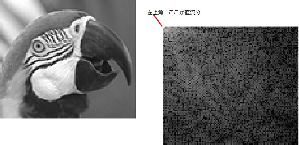 COS変換の場合、角度ゼロの時、1なので、変換された値は、直流分から始まり順に高い周波数になります。
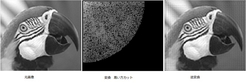
左上角が、画像全体の直流分となります、各ラインの先頭がそのラインの直流分です。
逆変換時は、直流分にたいする計算を別にする必要があります。
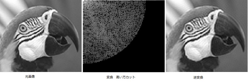 試しに高い方の周波数をカットしてみました。
逆変換した結果、元画像に対して全く遜色ない画像となっています。
実用的には、もっとカットしても問題ありません。
この特性が画像圧縮の元となっているようです。
次にSIN変換のテストをしてみます。
COS変換との差を見るためです。
プログラムは、単にCosをSinにするだけですが、直流分が分散されるので、逆変換時、直流分の計算は特に行っていません。
プログラム SIN変換
// Sin変換
// inv False 変換 True 逆変換
procedure TForm1.DST(var real: D2array; inv: boolean);
var
  M2                : Double;
  norm              : Double;
  Tre               : D2array;
  WrTable           : D2array;
  HrTable           : D2array;
  i, j, y, x, xx, yy: Integer;
begin
  // 作業用配列確保
  SetLength(Tre, X_SIZE, Y_SIZE);
  SetLength(WrTable, X_SIZE, X_SIZE);
  SetLength(HrTable, Y_SIZE, Y_SIZE);

  // X軸方向DST
  M2 :=   PI / X_SIZE;
  norm := sqrt(2.0 / X_SIZE);
  // 変換sinテーブル生成 直流、低い周波数から 高いほうへ設定
  for i := 0 to X_SIZE - 1 do
    for j := 0 to X_SIZE - 1 do
      if inv then Wrtable[i][j] := sin(M2 * (i + 0.5) * j)
             else Wrtable[i][j] := sin(M2 * (j + 0.5) * i);
  // y軸毎に変換
  for y := 0 to Y_SIZE - 1 do
    // 一次元DST
    for x := 0 to X_SIZE - 1 do begin
      Tre[x][y] := 0.0;
      for xx := 0 to X_SIZE - 1 do
        Tre[x][y] := Tre[x][y] + real[xx][y] * Wrtable[x][xx];
      Tre[x][y] := Tre[x][y] * norm;
    end;

  // Y軸方向DST
  M2 :=   PI / Y_SIZE;
  norm := sqrt(2.0 / Y_SIZE);
  // 変換sinテーブル生成 直流、低い周波数から 高いほうへ設定
  for i := 0 to  Y_SIZE - 1 do
    for j := 0 to Y_SIZE - 1 do
      if inv then Hrtable[i][j] := sin(M2 * (i + 0.5) * j)
             else Hrtable[i][j] := sin(M2 * (j + 0.5) * i);
  // X軸毎に変換
  for x := 0 to X_SIZE - 1 do
    // 一次元DST
    for y := 0 to Y_SIZE - 1 do begin
      real[x][y]  := 0.0;
      for yy := 0 to Y_SIZE - 1 do
        real[x][y]  := real[x][y] + Tre[x][yy] * Hrtable[y][yy];
      real[x][y] := real[x][y]  * norm;
    end;
end;
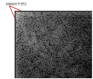 SINの値はゼロから始まるので、周波数ゼロの成分がゼロになってしまいます。
要するに直流成分が、周波数の値の中に分散します。
 高い方の周波数をカットすると、分散された直流分もカットしてしまうので縦横に1ラインごとに縞模様が入った画像となります。
カットしなければ、当然元の画像の再現ができます。
SIN変換は圧縮には利用されません。
90°ずらしてSIN変換すればSINでも使えますが、これはCOSの計算になります。
プログラム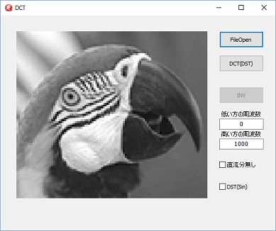 プログラムは、COS変換、SIN変換の両方が可能です。
データー圧縮の為のCOS変換の確認プログラムなので保存はありません。
チェックボックスのDSTにチェックを入れると、SIN変換になり、チェックが無ければCOS変換です。
直流分無しのチェックは、COS変換の時のみ有効で、全体の直流分(real[0,0])の値をゼロにします。
三色分配列を作って変換すればカラー化も可能です。
プログラムは、低い方の周波数のカットも出来る様になっていますが、あまり意味はありません。
unit DctMain;

interface

uses
  Winapi.Windows, Winapi.Messages, System.SysUtils, System.Variants, System.Classes, Vcl.Graphics,
  Vcl.Controls, Vcl.Forms, Vcl.Dialogs, Vcl.ExtDlgs, Vcl.ExtCtrls, Vcl.StdCtrls, System.Math;

type
  D2array = array of array of Double;
  B2array = array of array of Byte;

  TForm1 = class(TForm)
    FileOpenBtn: TButton;
    Image1: TImage;
    OpenPictureDialog1: TOpenPictureDialog;
    DCT2Btn: TButton;
    INVBtn: TButton;
    LabeledEdit1: TLabeledEdit;
    LabeledEdit2: TLabeledEdit;
    CheckBox1: TCheckBox;
    CheckBox2: TCheckBox;
    procedure FormCreate(Sender: TObject);
    procedure FormDestroy(Sender: TObject);
    procedure FileOpenBtnClick(Sender: TObject);
    procedure DCT2BtnClick(Sender: TObject);
    procedure INVBtnClick(Sender: TObject);
    procedure CheckBox2Click(Sender: TObject);
  private
    { Private 宣言 }
    procedure DCT(var real: D2array; inv: boolean);
    procedure DST(var real: D2array; inv: boolean);
    procedure DCT2Disp(real: D2array);
    procedure INVfilter(real: D2array);
  public
    { Public 宣言 }
  end;

var
  Form1: TForm1;

implementation

{$R *.dfm}

const
  OpenFileFilter =
    '画像ファイル|*.png;*.jpg;*.gif;*.bmp;*.tif;*.ico;*.wdp'+
    '|*.png|*.png' +
    '|*.jpg|*.jpg' +
    '|*.gif|*.gif' +
    '|*.bmp|*.bmp' +
    '|*.tif|*.tif' +
    '|*.ico|*.ico' +
    '|*.wdp|*.wdp';

  SaveFileFilter =
    '画像ファイル|*.png;*.jpg;*.gif;*.bmp;*.tif;*.wdp' +
    '|*.png|*.png' +
    '|*.jpg|*.jpg' +
    '|*.gif|*.gif' +
    '|*.bmp|*.bmp' +
    '|*.tif|*.tif' +
    '|*.wdp|*.wdp';

  ImageHW   = 384;    // 表示枠サイズ

var
  InputDBitmap  : TBitmap;                    // 入力データー表示用ビットマップ
  OutputBitmap  : TBitmap;                    // 回転画像表示用ビットマップ
  X_SIZE        : Integer;                    // 入力データー画像高さ
  Y_SIZE        : Integer;                    // 入力データー画像幅

  VRect         : Trect;                      // 表示サイズ設定用
  InFilename    : string;                     // 入力ファイル名
  GrayMat       : B2array;                    // グレー用配列
  OutDMat       : B2array;                    // 画像出力用配列
  real          : D2array;
const
  kr  = 0.299;                     // R 輝度変換係数
  kg  = 0.587;                     // G 輝度変換係数
  kb  = 0.114;                     // B 輝度変換係数


// Sin変換
// inv False 変換 True 逆変換
procedure TForm1.DST(var real: D2array; inv: boolean);
var
  M2                : Double;
  norm              : Double;
  Tre               : D2array;
  WrTable           : D2array;
  HrTable           : D2array;
  i, j, y, x, xx, yy: Integer;
begin
  // 作業用配列確保
  SetLength(Tre, X_SIZE, Y_SIZE);
  SetLength(WrTable, X_SIZE, X_SIZE);
  SetLength(HrTable, Y_SIZE, Y_SIZE);

  // X軸方向DST
  M2 :=   PI / X_SIZE;
  norm := sqrt(2.0 / X_SIZE);
  // 変換sinテーブル生成 直流、低い周波数から 高いほうへ設定
  for i := 0 to X_SIZE - 1 do
    for j := 0 to X_SIZE - 1 do
      if inv then Wrtable[i][j] := sin(M2 * (i + 0.5) * j)
             else Wrtable[i][j] := sin(M2 * (j + 0.5) * i);
  // y軸毎に変換
  for y := 0 to Y_SIZE - 1 do
    // 一次元DST
    for x := 0 to X_SIZE - 1 do begin
      Tre[x][y] := 0.0;
      for xx := 0 to X_SIZE - 1 do
        Tre[x][y] := Tre[x][y] + real[xx][y] * Wrtable[x][xx];
      Tre[x][y] := Tre[x][y] * norm;
    end;

  // Y軸方向DST
  M2 :=   PI / Y_SIZE;
  norm := sqrt(2.0 / Y_SIZE);
  // 変換sinテーブル生成 直流、低い周波数から 高いほうへ設定
  for i := 0 to  Y_SIZE - 1 do
    for j := 0 to Y_SIZE - 1 do
      if inv then Hrtable[i][j] := sin(M2 * (i + 0.5) * j)
             else Hrtable[i][j] := sin(M2 * (j + 0.5) * i);
  // X軸毎に変換
  for x := 0 to X_SIZE - 1 do
    // 一次元DST
    for y := 0 to Y_SIZE - 1 do begin
      real[x][y] := 0.0;
      for yy := 0 to Y_SIZE - 1 do
        real[x][y]  := real[x][y] + Tre[x][yy] * Hrtable[y][yy];
      real[x][y] := real[x][y]  * norm;
    end;
end;

// Cos変換
// inv False 変換 True 逆変換
procedure TForm1.DCT(var real: D2array; inv: boolean);
var
  M2                : Double;
  norm              : Double;
  startX            : integer;
  Tre               : D2array;
  WrTable           : D2array;
  HrTable           : D2array;
  i, j, y, x, xx, yy: Integer;
begin
  // 作業用配列確保
  SetLength(Tre, X_SIZE, Y_SIZE);
  SetLength(WrTable, X_SIZE, X_SIZE);
  SetLength(HrTable, Y_SIZE, Y_SIZE);

  // X軸方向DCT
  M2 :=   PI / X_SIZE;
  norm := 1;
  startX := 0;
  if inv then begin
    norm := 2.0 / X_SIZE;
    startX := 1;
  end;
  // 変換テーブル生成 直流、低い周波数から 高いほうへ設定
  for i := 0 to X_SIZE - 1 do
    for j := startx to X_SIZE - 1 do begin
      if inv then Wrtable[i][j] := cos(M2 * (i + 0.5) * j)
             else Wrtable[i][j] := cos(M2 * (j + 0.5) * i);
//  変換テーブル計算式は下記ですが高速化の為割り算をなくしています
//      if inv then Wrtable[i][j] := cos(pi * j / 2 / X_SIZE * (2 * i + 1))
//             else Wrtable[i][j] := cos(pi * i / 2 / X_SIZE * (2 * j + 1));
    end;
  // y軸毎に変換
  for y := 0 to Y_SIZE - 1 do
    // 一次元DCT
    for x := 0 to X_SIZE - 1 do begin
      Tre[x][y] := 0.0;
      for xx := startx to X_SIZE - 1 do
        Tre[x][y] := Tre[x][y] + real[xx][y] * Wrtable[x][xx];
      if inv then Tre[x][y] := Tre[x][y] + real[0][y] * 0.5;    // 直流分
      Tre[x][y] := Tre[x][y] * norm;
    end;

  // Y軸方向DCT
  M2 :=   PI / Y_SIZE;
  if inv then norm := 2.0 / Y_SIZE;
  // 変換テーブル生成 直流、低い周波数から 高いほうへ設定
  for i := 0 to  Y_SIZE - 1 do
    for j := startx to Y_SIZE - 1 do begin
      if inv then Hrtable[i][j] := cos(M2 * (i + 0.5) * j)
             else Hrtable[i][j] := cos(M2 * (j + 0.5) * i);
//  変換テーブル計算式は下記ですが高速化の為割り算をなくしています
//      if inv then Hrtable[i][j] := cos(pi * j / 2 / Y_SIZE * (2 * i + 1))
//             else Hrtable[i][j] := cos(pi * i / 2 / Y_SIZE * (2 * j + 1));
    end;
  // X軸毎に変換
  for x := 0 to X_SIZE - 1 do
    // 一次元DCT
    for y := 0 to Y_SIZE - 1 do begin
      real[x][y] := 0.0;
      for yy := startx to Y_SIZE - 1 do
        real[x][y] := real[x][y] + Tre[x][yy] * Hrtable[y][yy];
      if inv then real[x][y] := real[x][y] + Tre[x][0] * 0.5;   // 直流分
      real[x][y] := real[x][y]  * norm;
    end;
end;

// パワースペクトル(実数の二乗、対数にします)
// 対数変換は黒一色になるのを防止するためです
procedure TForm1.DCT2Disp(real: D2array);
var
  spec      : D2array;
  Max       : Double;
  x, y      : Integer;
  col       : Integer;
  norm      : Double;
  knorm     : Double;
begin
  SetLength(spec, X_SIZE, Y_SIZE);
  max := 0;
  if CheckBox2.Checked then knorm := 1                            // DST
                       else knorm := 4 / (X_SIZE * Y_SIZE);       // DCT
  for x := 0 to X_SIZE - 1 do
    for y := 0 to Y_SIZE - 1 do begin
      // パワースペクトルに変換
      norm := real[x][y] * real[x][y] * knorm;
      if norm <> 0 then norm := ln(norm);     // 周波数数画像表示の為対数変換
      spec[x][y] := norm;                     // 1以下は対数で負数となる為次の画像変換で0となります
      if norm > max then max := norm;         // 最大値検索
    end;

// 画像データに書き込み
  for x := 0 to X_SIZE - 1 do
    for y := 0 to Y_SIZE - 1 do begin
      col := round(spec[x][y] / max * 255);   // 最大値を255に変換
      if col > 255 then col := 255;
      if col < 0   then col := 0;
      OutDMat[y, x] := col;
    end;
end;

// DCT, DST 選択
procedure TForm1.CheckBox2Click(Sender: TObject);
begin
  if CheckBox2.Checked then CheckBox1.Enabled := False
                       else CheckBox1.Enabled := True;
end;

// パワースペクトル画像表示
procedure TForm1.DCT2BtnClick(Sender: TObject);
var
  x, y        : Integer;
  PBA         : PBytearray;
  WP          : integer;
  r           : double;
  Flow, Fhigh : double;
  r00Back     : double;
begin
  val(LabeledEdit1.Text, Flow, x);
  if (x <> 0) or (Flow < 0) then begin
    application.MessageBox('低い方の周波数に間違いがあります。','注意', 0);
    exit;
  end;
  val(LabeledEdit2.Text, Fhigh, x);
  if (x <> 0) or (Fhigh < 0) then begin
    application.MessageBox('高い方の周波数に間違いがあります。','注意', 0);
    exit;
  end;
  if Flow >= Fhigh then begin
    application.MessageBox('高い方と低い方の値が逆です。','注意', 0);
    exit;
  end;
  // 周波数ゼロ(直流分)の設定
  DCT2Btn.Enabled := False;
  SetLength(real, X_SIZE, Y_SIZE);
  // 画像データーを配列にセット
  for x := 0 to X_SIZE - 1 do
    for y := 0 to Y_SIZE - 1 do
      real[x, y] := GrayMat[y][x];
  // スペクトル分析
  if CheckBox2.Checked then DST(real, False)
                       else DCT(real, False);
  // 周波数フィルターの実施 周波数範囲外を0にセット
  r00Back := real[0, 0];
  if CheckBox1.Checked and not CheckBox2.Checked then real[0, 0] := 0;
  for x := 0 to X_SIZE - 1 do
    for y := 0 to Y_SIZE - 1 do begin
      r := sqrt(x * x + y * y);
      if r < Flow  then real[x, y] := 0;
      if r > Fhigh then real[x, y] := 0;
    end;
  if not CheckBox1.Checked and not CheckBox2.Checked then real[0, 0] := r00Back;
  DCT2Disp(real);                  // 画面表示用に変換
  for Y := 0 to Y_SIZE - 1 do begin
    PBA := OutputBitmap.ScanLine[Y];
    for X := 0 to X_SIZE - 1 do begin
      WP := X * 3;
      PBA[WP]     := OutDMat[Y, X];
      PBA[WP + 1] := OutDMat[Y, X];
      PBA[WP + 2] := OutDMat[Y, X];
    end;
  end;
  Image1.Canvas.StretchDraw(VRect, OutputBitmap);     // 出力枠に変倍出力
  DCT2Btn.Enabled := True;
  INVBtn.Enabled := True;
end;

// 逆変換画像表示
procedure TForm1.INVfilter(real: D2array);
var
  x, y    : Integer;
  data    : Integer;
begin
  if CheckBox2.Checked then DST(real, true)             // 逆変換
                       else DCT(real, true);
  for x := 0 to X_SIZE - 1 do
    for y := 0 to Y_SIZE - 1 do begin
      data := round(real[x, y]);
      if data > 255 then data := 255;
      if data < 0   then data := 0;
      OutDMat[y, x] := data;
    end;
end;

// 逆変換表示
procedure TForm1.INVBtnClick(Sender: TObject);
var
  x, y        : Integer;
  PBA         : PBytearray;
  WP          : integer;
begin
  INVBtn.Enabled := False;
  INVfilter(real);
  // 逆変換画像表示
  for y := 0 to Y_SIZE - 1 do begin
    PBA := OutputBitmap.ScanLine[Y];
    for x := 0 to X_SIZE - 1 do begin
      WP := X * 3;
      PBA[WP]     := OutDMat[y, x];
      PBA[WP + 1] := OutDMat[y, x];
      PBA[WP + 2] := OutDMat[y, x];
    end;
  end;
  Image1.Canvas.StretchDraw(VRect, OutputBitmap);    // 出力枠に変倍出力
end;

// ファイルのオープン及び輝度変換
procedure TForm1.FileOpenBtnClick(Sender: TObject);
var
  WIC         : TWICImage;
  IHeight     : Integer;
  IWidth      : Integer;
  X, Y        : Integer;
  PBA         : PBytearray;
  PFD, WP     : Integer;
begin
  INVBtn.Enabled := False;
  DCT2Btn.Enabled := False;
  VRect := Rect(0, 0, Image1.Width, Image1.Height);
  Image1.Canvas.Brush.Style := bsSolid;
  Image1.Canvas.Brush.Color := clBtnface;
  Image1.Canvas.FillRect(VRect);                              // Canvas 画像消去
  OpenPictureDialog1.Filter := OpenFileFilter;                // ファイルオープンフィルターの設定
  if OpenPictureDialog1.Execute then                          // ファイルが指定されたら
    begin
      WIC := TWICImage.Create;                                // TWICImageの生成
      try
        InFilename := OpenPictureDialog1.FileName;            // ファイル名の取得
        WIC.LoadFromFile(InFilename);                         // 画像の読み込み
        Y_SIZE  := WIC.Height;                                // 画像高さ取得
        X_SIZE  := WIC.Width;                                 // 画像幅
        IWidth  := ImageHW;                                   // 出力先イメージ1の幅
        IHeight := ImageHW;                                   // 出力先イメージ1の高さ
        if Y_SIZE <= X_SIZE then                              // 縦横比により出力サイズ設定
          IHeight := Round(IWidth * Y_SIZE / X_SIZE)
        else
          IWidth := Round(IHeight * X_SIZE / Y_SIZE);
        Image1.Width := IWidth;
        Image1.Height:= IHeight;
        Image1.Picture.Bitmap.SetSize(IWidth, IHeight);
        VRect := Rect(0, 0, IWidth, IHeight);                 // 出力枠設定
//        Image1.Canvas.StretchDraw(VRect, WIC);                // 出力枠に変倍出力
        InputDBitmap.Assign(WIC);                             // Tbitmap に TWICImageをコピー
      finally
        WIC.Free;                                             // TWICImage 解放
      end;
    end
    else exit;
  OutputBitmap.Width  := X_SIZE;
  OutputBitmap.Height := Y_SIZE;
  setLength(GrayMat, Y_SIZE, X_SIZE);
  setLength(OutDMat, Y_SIZE, X_SIZE);
  PFD := 3;
  if InputDBitmap.PixelFormat = pf32bit then PFD := 4;
  for Y := 0 to Y_SIZE - 1 do begin
    PBA := InputDBitmap.ScanLine[Y];
    for X := 0 to X_SIZE - 1 do begin
      WP := X * PFD;
      GrayMat[Y][X] := Round(PBA[WP] * kb + PBA[WP + 1] * kg + PBA[WP + 2] * kr); // 輝度データーに変換
    end;
  end;
  for Y := 0 to Y_SIZE - 1 do begin
    PBA := OutputBitmap.ScanLine[Y];
    for X := 0 to X_SIZE - 1 do begin
      WP := X * 3;
      PBA[WP]     := GrayMat[Y][X];
      PBA[WP + 1] := GrayMat[Y][X];
      PBA[WP + 2] := GrayMat[Y][X];
    end;
    Image1.Canvas.StretchDraw(VRect, OutputBitmap);           // 出力枠に変倍出力
  end;
  DCT2Btn.Enabled := True;
end;

procedure TForm1.FormCreate(Sender: TObject);
begin
  Image1.Width  := ImageHW;
  Image1.Height := ImageHW;
  InputDBitmap  := TBitmap.Create;
  OutputBitmap  := TBitmap.Create;
  InputDBitmap.PixelFormat := pf24bit;
  OutputBitmap.PixelFormat := pf24bit;
  INVBtn.Enabled := False;
  DCT2Btn.Enabled := False;
end;

procedure TForm1.FormDestroy(Sender: TObject);
begin
  InputDBitmap.Free;
  OutputBitmap.Free;
end;

end.
![]() discrete_cosine_transform.zip
discrete_cosine_transform.zip